


HOME > PRODUCT
 Product introduction
- IP1826D
- 24-port 10/100M + 2-port Gigabit Smart Switch Controller
General Description
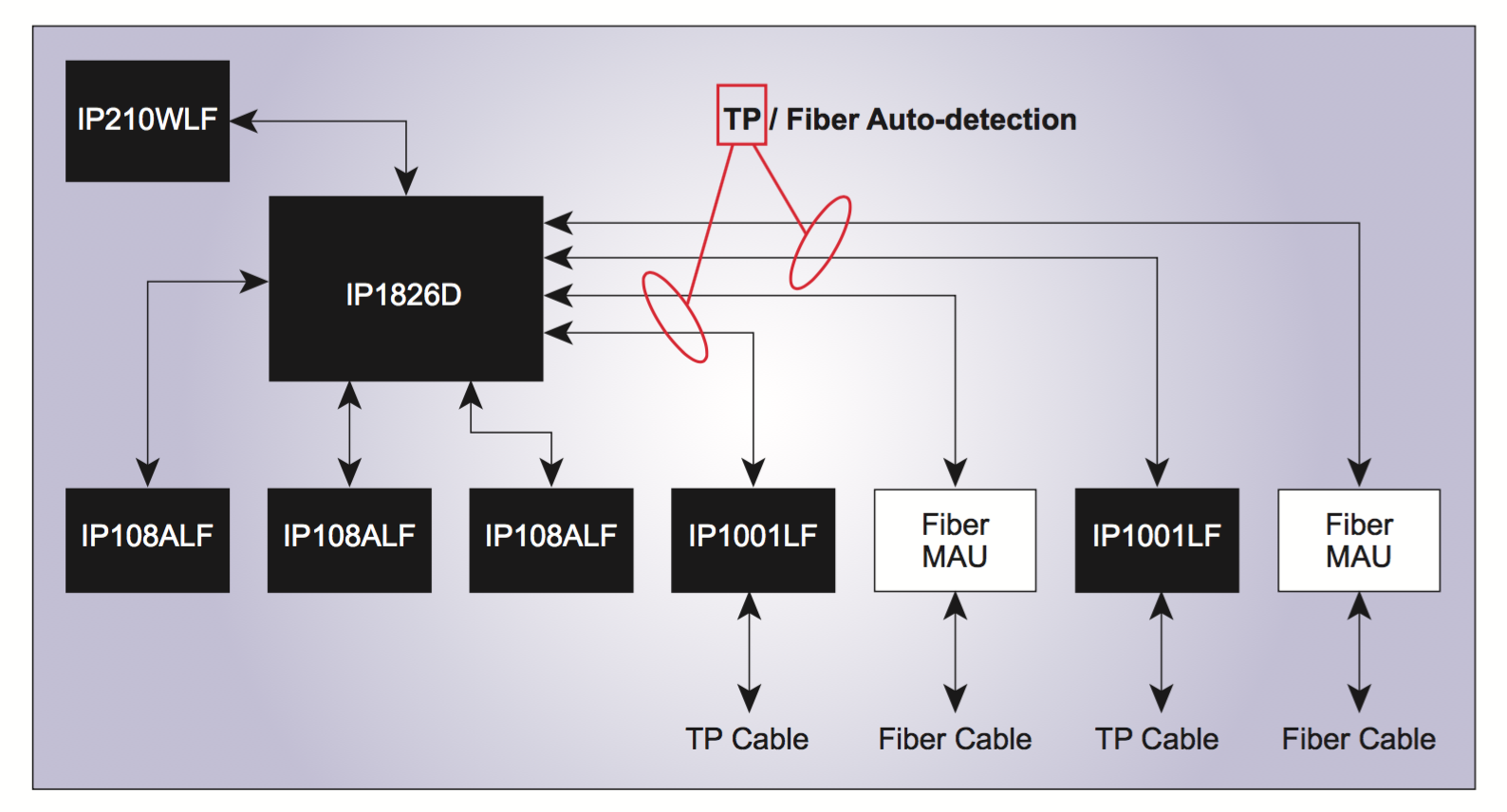
The IP1826D is a non-blocking, store-and-forward architecture switch controller, which supports 24-port SS-SMII, 2-port RGMII/ SERDES, and one-port MII for a 24+2G smart switch application. With two built-in SERDES transceiver, The IP1826C provides a very cost-effective solution for a 24+2 Gigabit fiber without external Gigabit Ethernet transceivers.
Note: In the following paragraphs, 24-port SS-SMII is referred to as port 0 ~ port 23, 2-port RGMII as port 24 and port 25 and MII port as port 26 (P0 ~ P26 in abbreviation). The PHY address for P0 ~ P23 are “8~31” respectively. The PHY address “1” and “2” correspond to P24 and P25 respectively.
The IP1826D embeds a 2.75Mb SSRAM for the use of packet buffer and 4K MAC address table. It provides a 2-wire CPU interface, which allows the designer to access to the register in IP1826C itself, the external PHY’s and the EEPROM. The LED informations is provided through a 2-wire LED interface by IP1826C. With the external logic devices, the IP1826C can show the status of link, speed, duplex and activity.
In addition to the fundamental function such as the flow control, the broadcast storm control and the programmable MAC address aging time, the IP1826C also supports many advanced features which allow the designer to implement the smart switch features. The IGMP (Internet Group Management Protocol) snooping provides a method to build a multicast link without complicated CPU code. The designer can also use the 2 levels of priority queue to support the real-time streaming application. Supporting both port_based and tag_based VLAN, the IP1826C can partition the network traffic by programming the VLAN table. The access control based on the MAC layer, the IP layer and TCP/UDP layer provides a method for the designer to implment the Class of Service and the network security.
The web management software ported on IP210, an ICPLUS 8051 based web controller, is provided for the designer to easily design a web management smart swicth. With the web management function, designers can remotely configure and monitor IP1826C smart switches through browsers, such as Microsoft Internet Explorer, and no extra program is needed.
Features
Provides 24 SS-SMII, 2 RGMII, 2 SERDES for fiber cable and one MII
Built-in 2.75Mb RAM
Support packet length up to 1536 Bytes
Store & forward, share memory, non-blocking architecture
Supports flow control
802.3x in full duplex
Collision/carrier_sense based
backpressure in half duplex
Provides up to 4K MAC address entries
CRC/ direct hashing algorithm
Programmable aging timer (55s~15.7hr) error < 4 %
Configurable MAC address table Optional MAC address learning
IP filter
Supports porting mirroring function (in, out,in&out)
Supports IGMP snooping function
Version 1, 2
Supports flexible 3 trunking groups
(Port 0~3, port 4~7, Gigabit port 1 ~2)
Load balance based on (port, DA, SA, DA/SA)
Link failure recovery
Supports VLAN
Port based VLAN
Tag based VLAN
- Add/ remove/ modify tag
Support Class of Service
Port based CoS
802.1Q priority tag based
IP TOS based (IPv4/IPv6)
TCP/UDP port based
2 level per port
WRR/ First-Come-First-serve/ Srict
Priority algorithm
Broadcast storm control support
Broadcast rate control per chip
Block broadcast packet that does not belong to ARP or IP packet forwarded to CPU port
Supports port security
MAC address based
IP address based
TCP/UDP port based
Supports Bandwidth control
480 configurable levels for p0~p23 and MII port (from 32kbps to 63.75 Mbps)
508 configurable levels for RGMII port (from 32kbps to 510 Mbps) With/without flow control
Supports 5 port state for Spanning Tree protocol
Blocking/ listening/ learning/ forwarding/ disable
Forward BPDU to CPU port
Captures specific packet to CPU port
BPDU, LACP, 802.1x, GMRP, GVRP, ARP
ICMP, IGMP, TCP, UDP, OSPF
Packets with specific TCP/UDP port number
PHY address setting for CPU, giga 1 and giga2 port
Operating mode configuration
Pin initial setting
2 wire serial interface for EEPROM
2 wire serial interface for CPU
Counters for each port
RX/TX packet count
CRC error packet count
Dropped packet count
Collision count
Programmable serial driving LED functions
Only one 25MHz crystal is needed
Optional 25Mhz, 50Mhz clock output
Adjustable IO voltage (3.3/2.5v MII, 3.3/1.8vSS-SMII, 2.7~1.9V RGMII)
Built-in 2.5v and 1.9 regulator
144 pin EP AD. Lead-free package
Technical reference
Data download
Warning: Invalid argument supplied for foreach() in /www/wwwroot/cybertop.com.cn/en/product_detail.php on line 93